Intro
I had been eyeing a CNC machine for a long time, particularly for woodworking, but had often been put off by the high prices and limited work area. I had hoped to build bigger furniture, MTB trail features, etc., so a small desktop CNC wouldn’t do. But I also didn’t want to spend tens of thousands on a CNC I would just use for hobby and house projects.
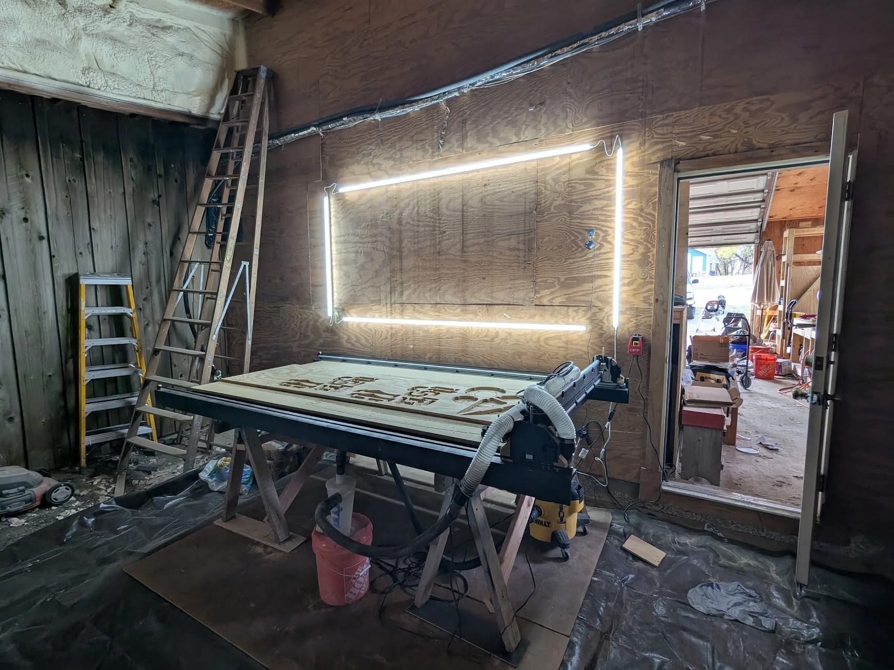
I first came across DIY CNC builds through the Maslow portable CNC, a small sled-and-wire-based machine. Later, I learned about the Lowrider V4 CNC and decided to build one. It’s mostly 3D-printed and can cut full 4×8 sheets of plywood. The whole build, including the table and router, cost me around $1k.
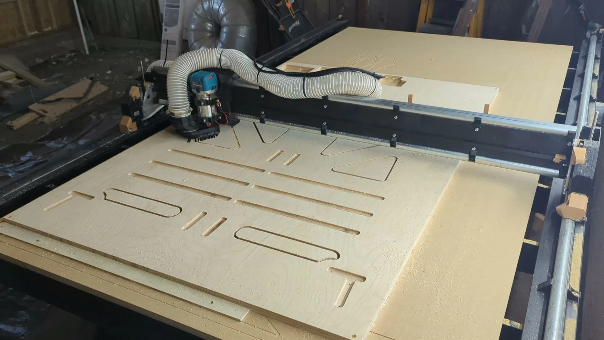
Setting the hardware aside, to use a CNC you need CAM software, which creates toolpaths for the machine to follow. Many CNC machines use G-code, the same simple command language used by 3D printers. It’s a very simple programming language where each line gives the machine a command, like “Do a rapid move to X:350 and Y:400, then lower the cutting head to Z:-20 at 600mm/minute and then move the cutting head to X:450 at 1500mm/min.”
; --- START OF PROGRAM & INITIALIZATION ---
G21          ; Set units to millimeters
G90          ; Use absolute positioning coordinates
G17          ; Select the XY cutting plane
G28          ; Home all axes to clear the workspace safely

; --- SETUP SPEEDS AND TOOLING ---
M03 S1200    ; Turn spindle ON (clockwise) at 1200 RPM
G00 X0 Y0 Z5 ; Rapid move to X0, Y0, while keeping tool 5mm above material

; --- BEGIN CUTTING ---
G01 Z-2 F100 ; Plunge tool 2mm deep into material at a feed rate of 100 mm/min
G01 X40 F300 ; Cut a straight line to X=40 at an increased cutting speed (300 mm/min)
G01 Y40      ; Cut a straight line to Y=40 (G01 and F300 remain active)
G01 X0       ; Cut a straight line back to X=0
G01 Y0       ; Cut a straight line back to Y=0 (Square completed)

; --- RETRACT AND SHUTDOWN ---
G00 Z5       ; Rapidly lift the tool 5mm out of the material
M05          ; Stop the spindle
G28          ; Return the tool back to home position safely
M30          ; End of program, reset memory
There are a few different pieces of software for this—both paid and free—including Estlcam and Fusion 360. However, one gripe I had with these programs was that they weren’t procedural, so I had to remember my setup and settings.
More than once, I’d make some cuts and run into an issue—wrong speeds and feeds, forgotten tabs, or margins that needed adjusting to fit tight pieces. Then I’d have to redo the whole setup, which often introduced other issues.
Naturally, I thought about how much easier it would be to approach this in a procedural graph in Houdini. If there were issues I could tweak it anywhere in the pipeline, without having to rebuild the rest. It would also allow me to implement custom features as I needed them.
→ SO I GOT TO WORK.
Basic G-code from Houdini Geo
There was already some precedent here. Entagma did a basic video on how to control a 3D printer via Houdini. That got me started, and through research and some help from a friendly LLM, I figured out how to approach the part that felt most “foreign” to me: going from Houdini geometry to G-code and back.
The general idea is quite simple. G-code is represented by simple polylines inside Houdini. Each point already has a position, and attributes store things like the movement type (rapid vs. cutting, G0/G1) and speed (F). Then a simple Python script traverses the points and writes the information to a simple .gcode text file.
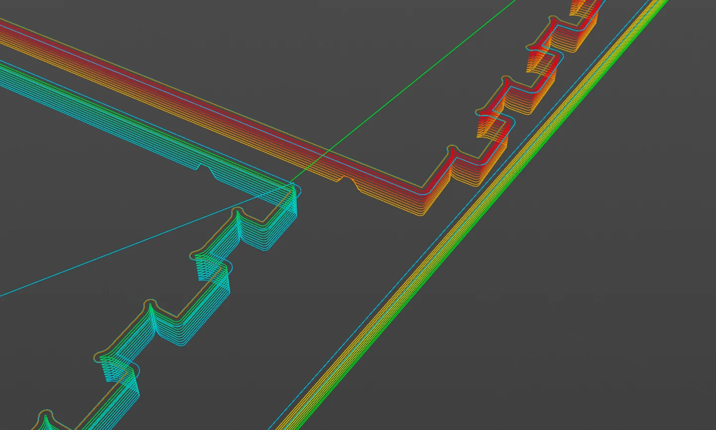
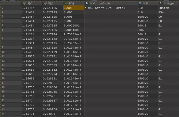
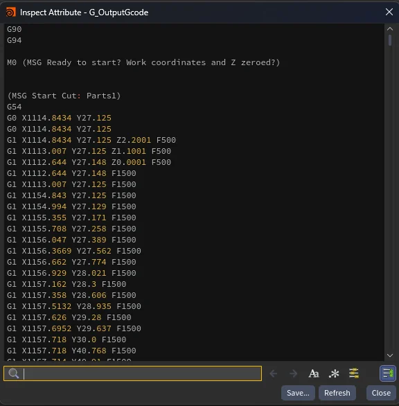
So far, so good. Things get a little more complicated when you move from simple shapes to creating real toolpaths.
Holes and Parts
One of the most common woodworking tasks is cutting shapes out of plywood and flat stock. Again, this is pretty straightforward:
Input shape → offset the path by half the cutter-head width → export G-code.
I first tried Houdini’s own inset tool (extrude node) and the 2D expand node. Both worked in some situations, but each had edge cases where it failed or needed a lot of manual tweaking.
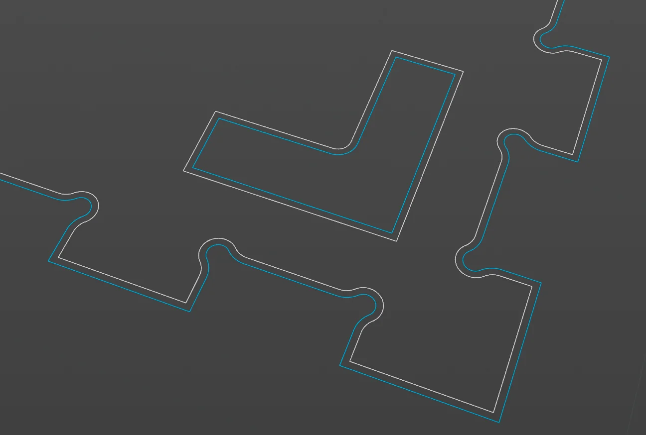
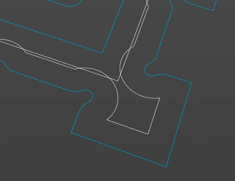
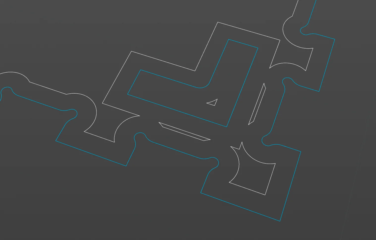
As I kept trying different setups, I ran into other cases where the 2D expand tool failed—especially when it came to pocketing. For example the polyexpand 2D tool cannot handle any overlapping curves. There also weren’t any options for how to handle “lines” and corners etc. There also seemed to be no good option for robust 2d boolean operations for flat curves in houdini (think the pathfinder tools in illustrator). There were some workarounds like extruding the geo, so I could do 3D boolean and then slice it back into a 2D shape, which worked sometimes but also was slow at times or would often fail.
Luckily, I came across an amazing library that was pretty much bulletproof, no matter what curves you throw at it: Clipper2 - Polygon Clipping Offsetting & Triangulating. It’s a C++ toolset, but luckily someone created Python bindings for it! https://github.com/drlukeparry/pyclipr
With the Pyclipr Python wheel, some basic conversion of Houdini geometry to the format expected by the Pyclipr API, and a bit of extra geometry prep inside the HDAs, I was quickly able to take full advantage of the toolset. You can find it here:
https://github.com/handcraftedcc/Houdini-Curve-Clipper
The end results were two nodes, CurveClipper Boolean and Offset.
Besides being mostly bulletproof, the nodes also offer many options, like different Boolean modes and corner/end modes for curves (round, square, miters, etc.).
It took quite a bit more to get everything working just right—processing the input, managing different parts and moves between them, and setting up plunge angles (so the bit eases down at an angle instead of drilling straight down). But, generally speaking, holes and parts were pretty straightforward with the CurveClipper toolset.
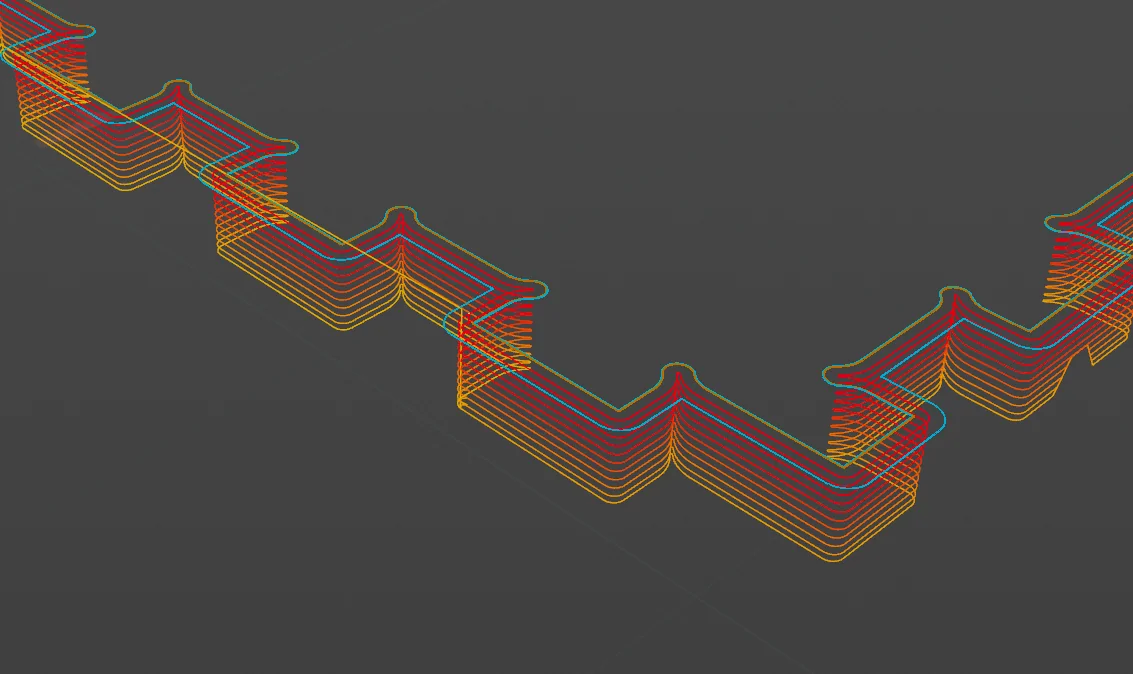
Once you have the offset curves you then just “duplicate them and offset them downwards”, creating a cut in multiple passes.
Tabs
When cutting parts on a CNC, you’ll usually want tabs: small sections left uncut along each part’s edge. They keep the part from coming loose at the end of the cut, which could bind the bit or send the part flying across the room (not ideal). In practice, creating a tab just means lifting the cutting head over certain sections, leaving a small connection to the surrounding stock.
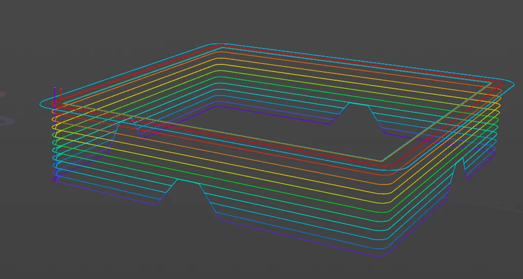
The solution actually ended up being pretty “primitive.” All I did was copy small wedges or boxes along the toolpath, then project the points “under” each wedge upward.
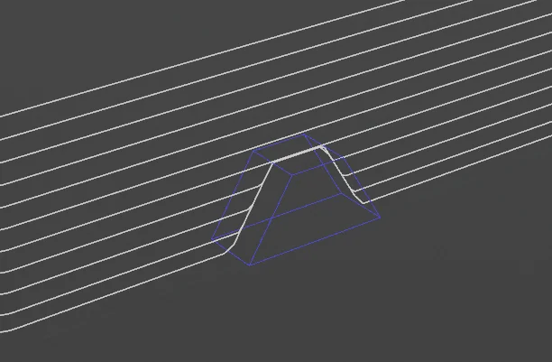
For this to work I did have to do some resampling of the curve before and after, but pretty simple overall.
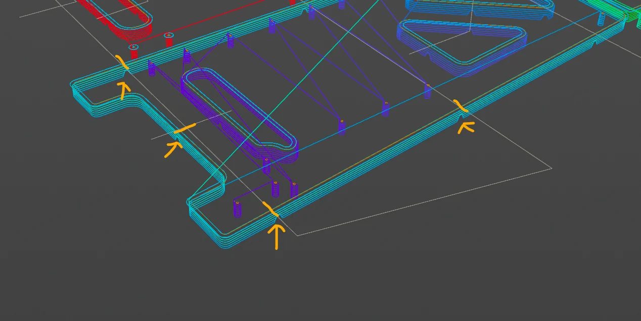
For placement of the tabs I implemented two options:
- Edge length - place a tab every X distance on straight sections longer than Y. This avoids pockets in curved sections that might be harder to clean up.
- Custom Input Curve - use a curve to direct the placement of the pockets (my goto). Basically, wherever the input curve intersects the cut, we place a pocket.
Pocketing
Pocketing is the process of clearing out full areas. So instead of just cutting a hole, by cutting along the outside the cutter moves back and forth throughout the whole area. This is used if you are making cuts that don’t go all the way through the workpiece (thus a “pocket”).
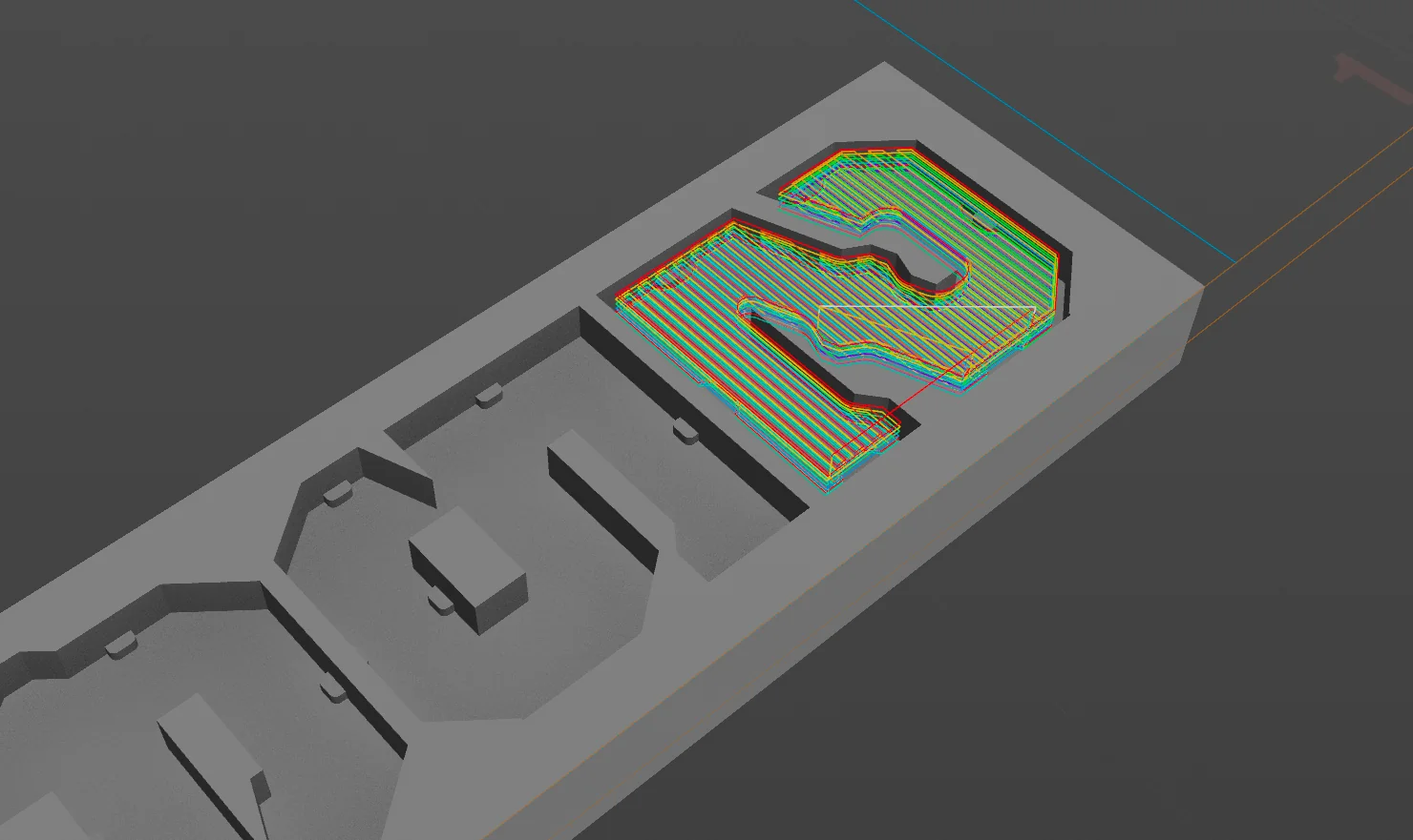
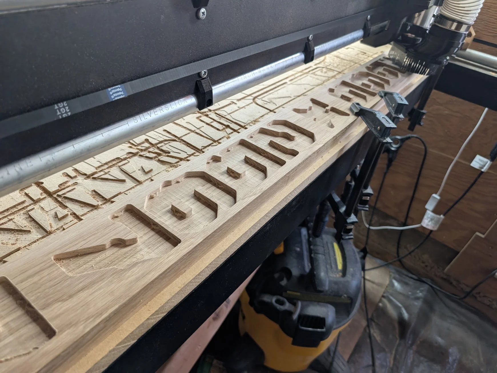
There are a few different popular methods/algorithms for this. The most popular, and probably most useful for wood is a “raster pocket”. This is where the tool moves in straight lines back and forth across the pocket area. Another method is called “parallel”, where you cut increasingly smaller (or bigger if you start at the center) lines offset to the outer and inner target paths.
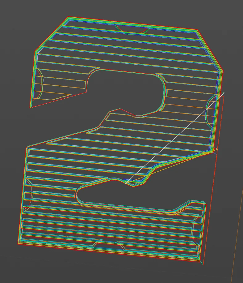
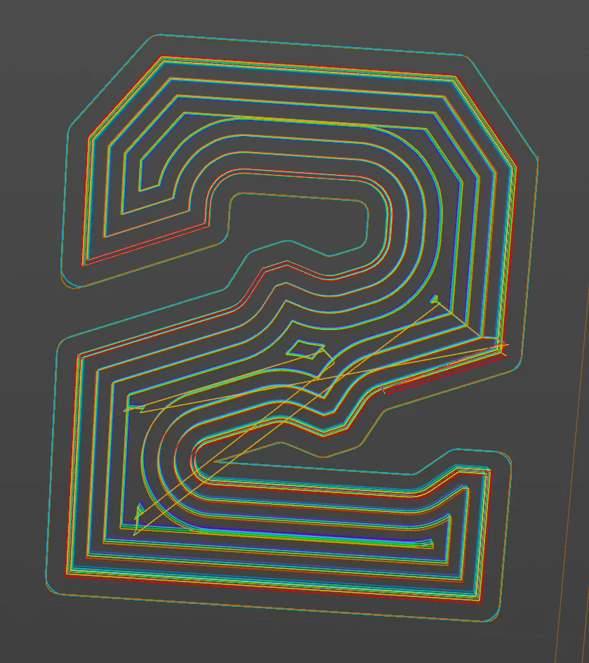
Algorithmically raster seems like the simpler option, however it took me a while and quite a few variations until I came up with the current algorithm. There are a bunch of things you want to optimize for:
- Keep as much of the cut as possible in one continuous motion, so the toolhead can move “back and forth” through the stock without lifting out.
- Minimize how often the toolhead has to “dive down” into the stock. In one continuous pocket, you shouldn’t have to start a new hole; instead, you should be able to “move sideways” from an area you’ve already cut.
- Move between the “sections” of the shape efficiently and minimize travel moves.
I tried some more complicated algorithms that split everything into branching sections, but the simplest solution that worked well—and felt very “Houdini-native”—was to:
- Slice the shape into lines based on its size, the cutter diameter, and the stepover (how much overlap you want between passes).
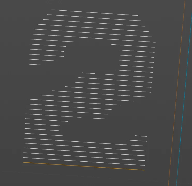
- Create a “travel path mesh” that combines the cutting passes and the outlines.
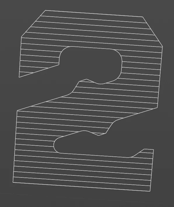
- Start with the first path at one end. Use the Find Shortest Path node to connect the current path’s endpoint to the start point of an uncut path, using the travel path mesh as the underlying geometry.
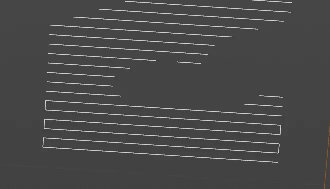
- Continue until all paths are covered.
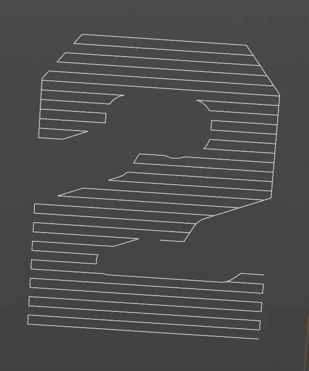
This does result in some “suboptimal” travel because the toolhead can’t move across paths. But it ended up being the simplest and most foolproof solution, with less complicated logic and fewer failure points than my previous attempts. It still has “pretty good” efficiency, without needing to lift, plunge, or make extra travel moves.
Parallel pocketing was pretty simple since our CurveClipper toolset can provide the offset paths basically for free. The process boils down to
- Create the toolpaths using the curvelipper offset tool
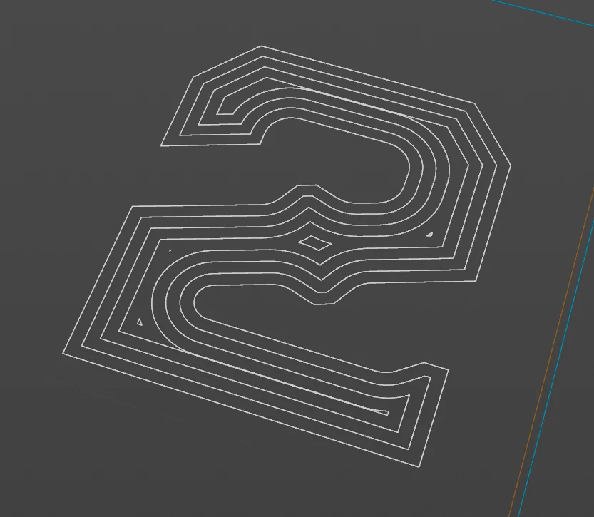
- Connect the paths together:
a. If the next path’s start point (whether we’re going outward in or inward out) is close to the current path’s endpoint, we can move directly. b. If the next path starts next to a section we’ve already cut, we travel there: raise the toolhead, move over rapidly, lower it to the closest existing cut point, and move sideways. c. If neither option works, we make a “new plunge cut,” drilling down into fresh stock.
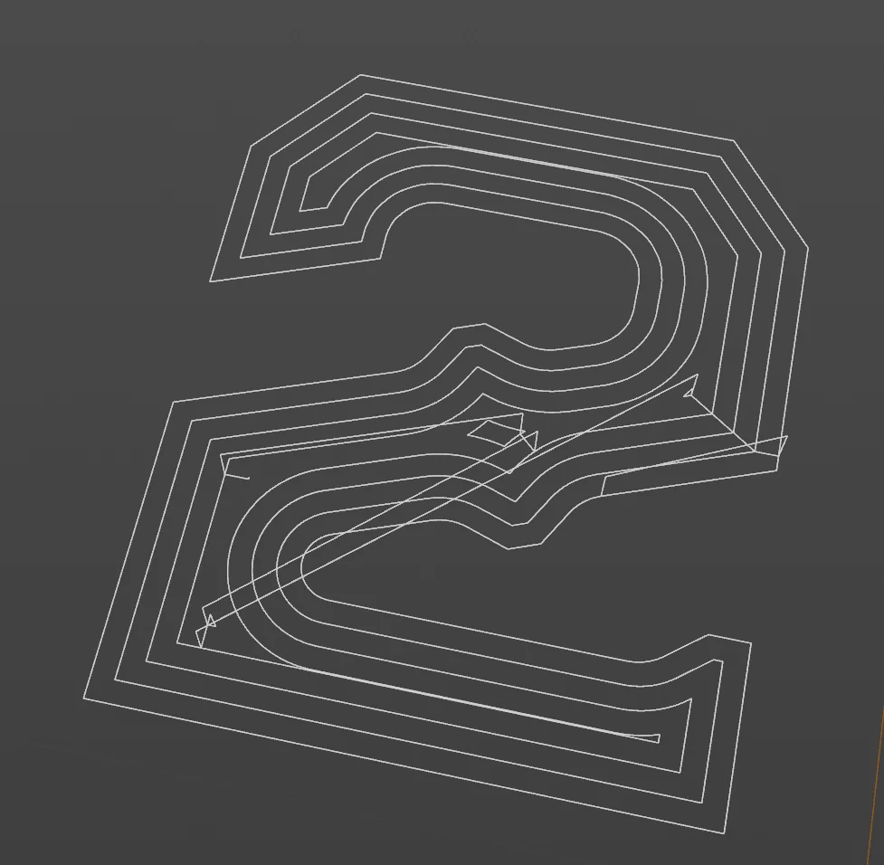
Connecting the parts together
All that’s really left is to connect the individual sections together with simple travel moves (raise the cutting head, move it to new position, plunge down into new area).
UI/UX
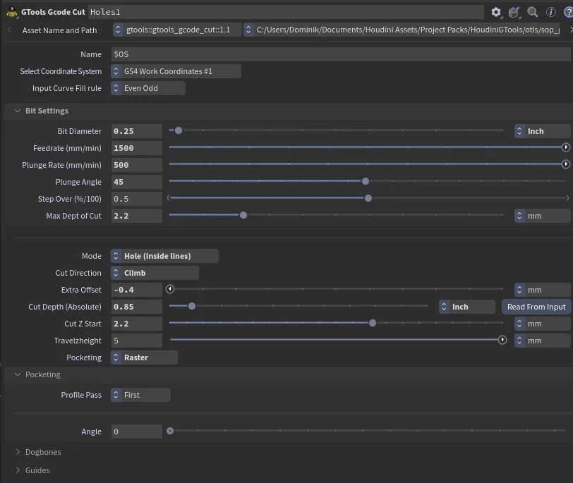
All of the above happens in a single Cut node, with standard bit settings (feeds and speeds, diameter, etc.), general cut settings (direction, total depth, etc.), tab and pocketing settings, and dogbones for corners the round bit can’t reach.
G-code Import & Output
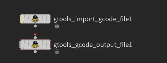
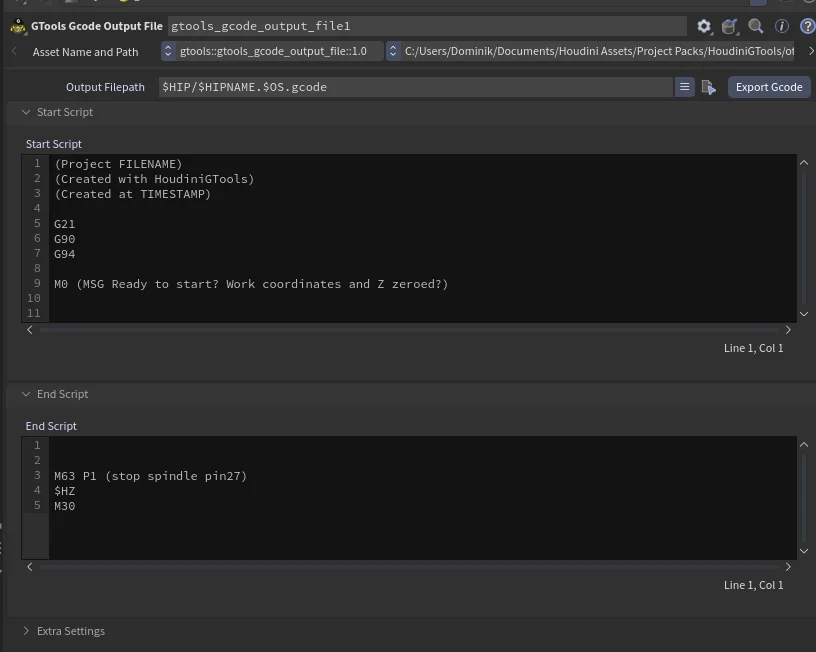
Of course, we need to be able to write G-code to a file that we can pass to our machine. This is handled by the G-code output file node.
Early on, I also had an LLM write a simple Python script to import G-code files so I could check or modify them.
Drill Tool
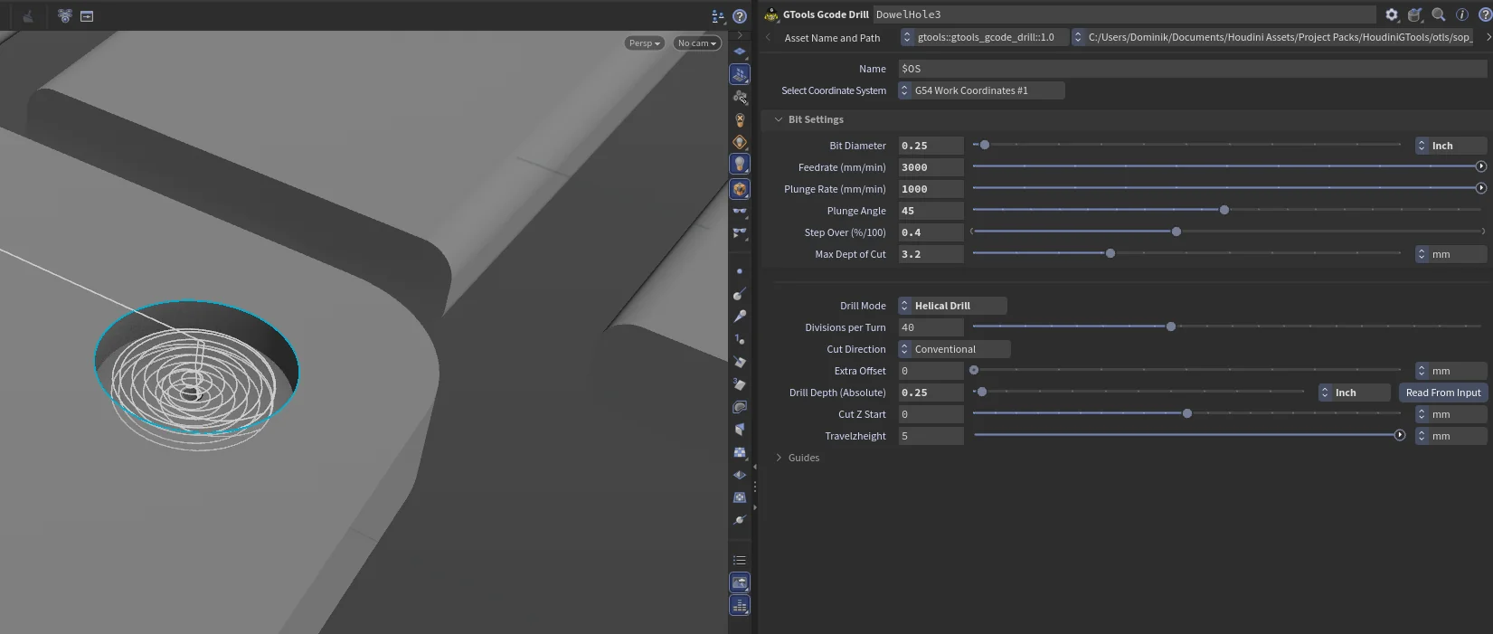
I also added a much simpler tool for drilling holes, both straight drilling and hellical holes.
Prep Utilities
While the cutting paths are the “most important” and complicated part of the process, there were quite a few user experience type things I wanted, that would make it easier to go from CAD model to toolpaths.
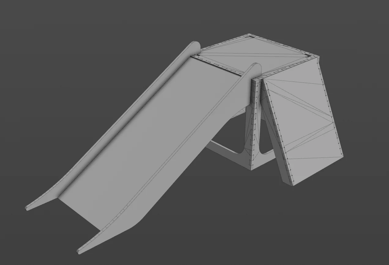
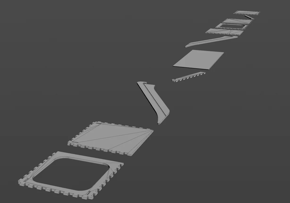
Lay Flat Tool
Automates taking geometry in its original position and laying each part flat so it’s ready to be cut from flat wood stock. Basically, it finds the largest continuous face of each part and rotates the part so that face lies flat.
Layout Tool
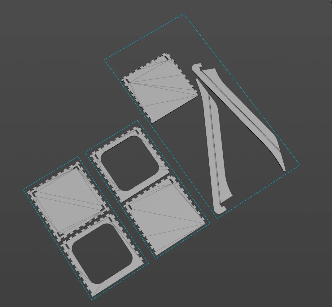
Uses Houdini’s UV layout tools to pack
Silhouette to Curves Tool
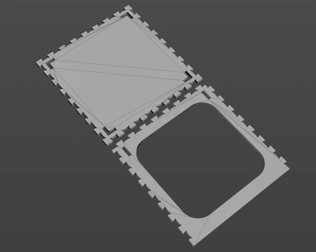
Converts a mesh into cutting curves based on its silhouette (useful for through cuts).
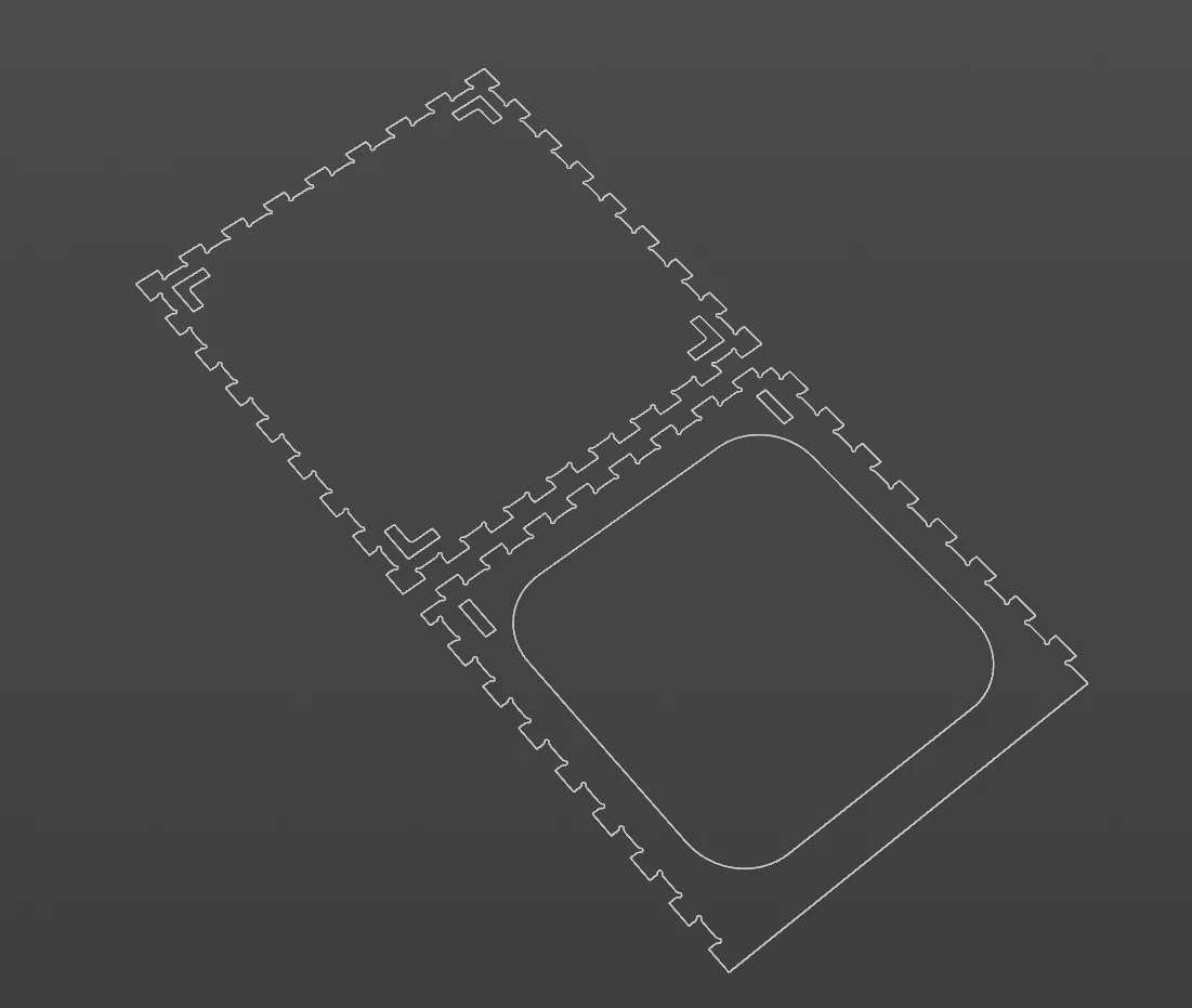
3D to curves
Converts the various surfaces to 3D curves—useful for pocketing, etc.
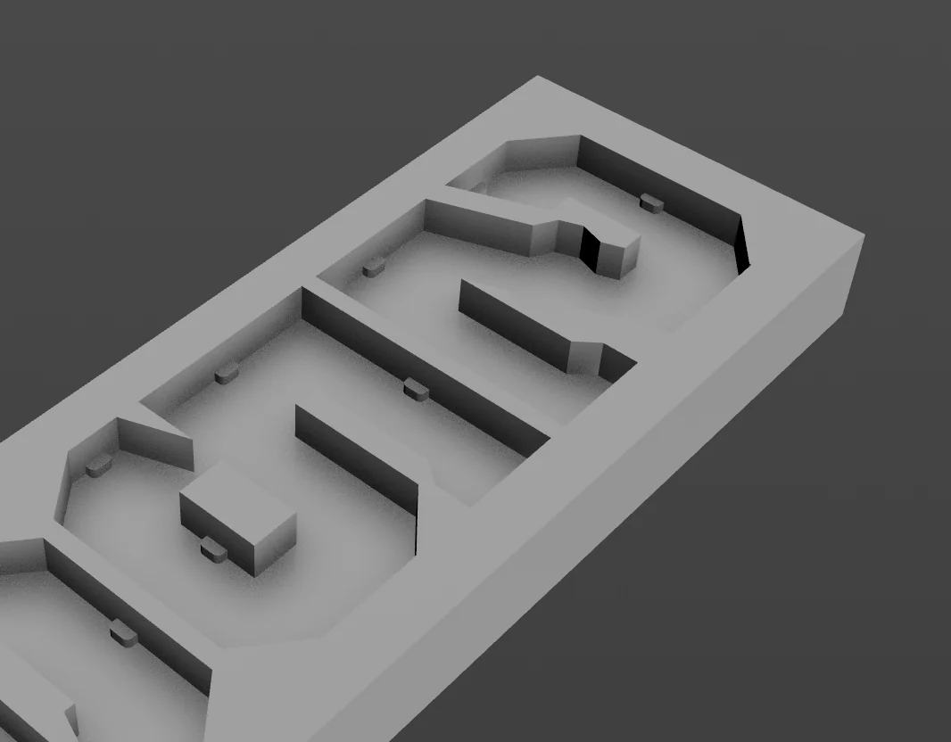
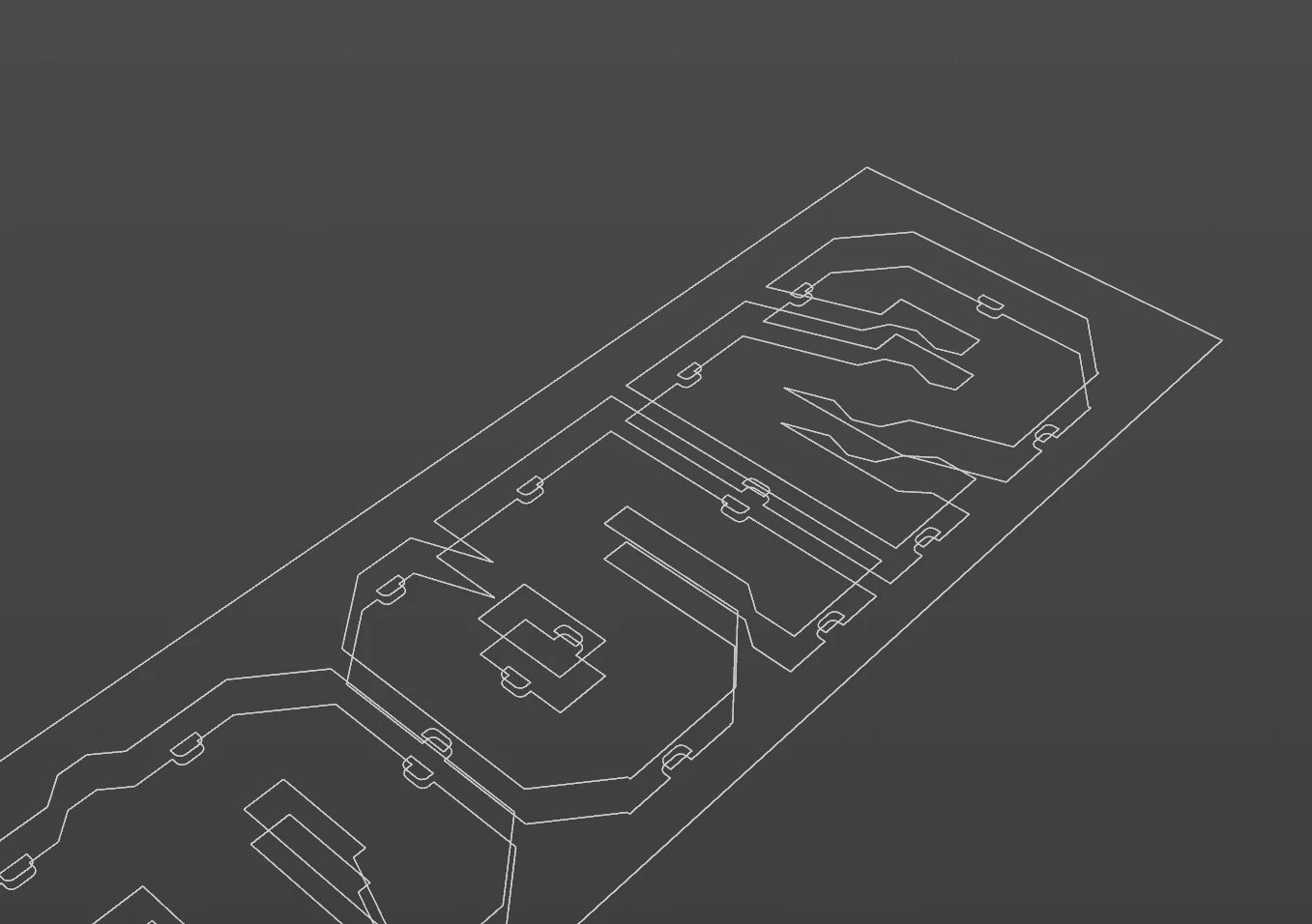
One nifty feature lets you set the cut depth from the curves’ 3D positions by reading their Z values, which makes setup easier.

Check Utilities
One of the most useful things is being able to spot issues before you even turn on your CNC.
Simulate Cut Tool
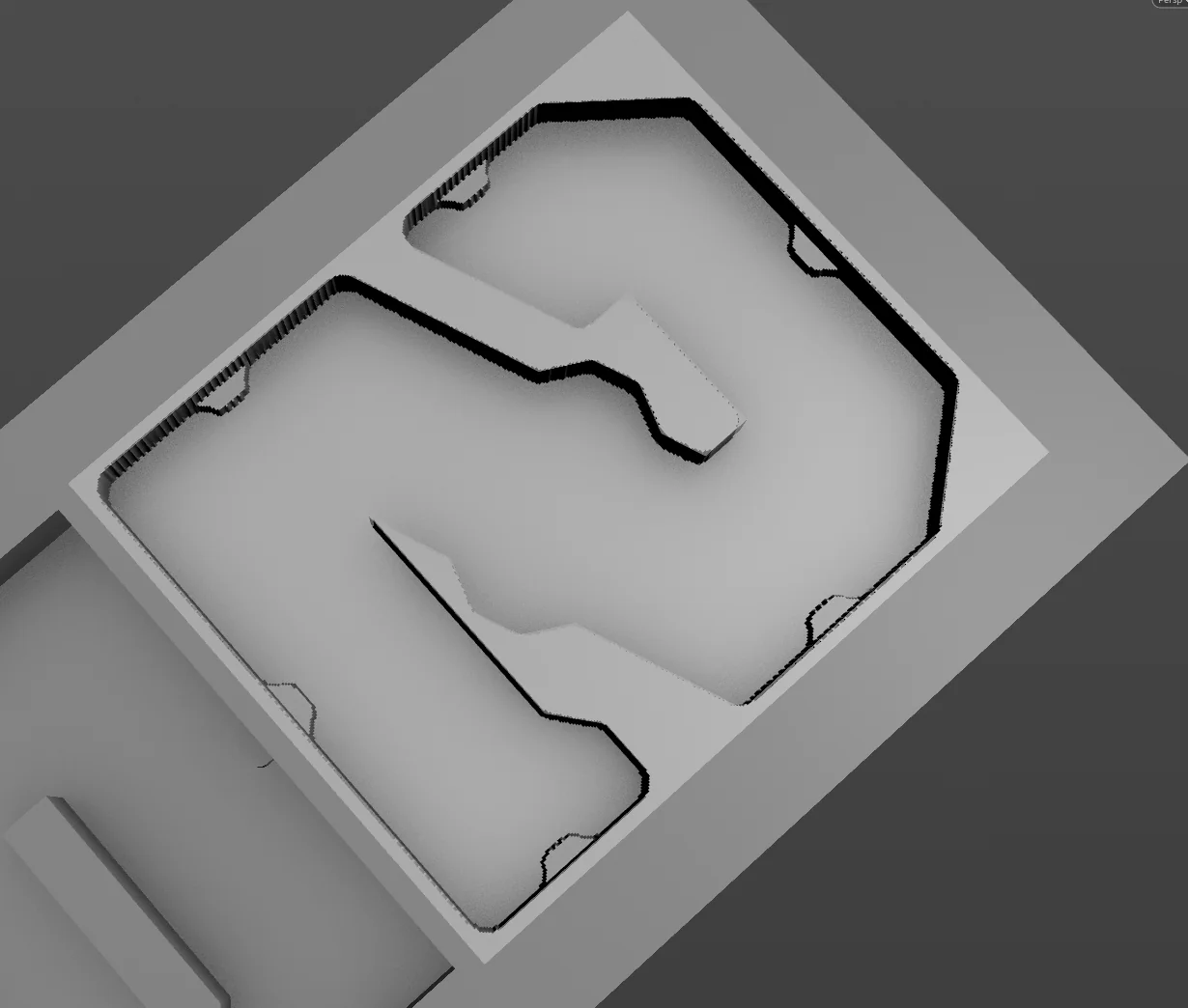
Simulates material removal by moving a virtual toolhead through a heightfield or VDB. This makes issues like bad travel moves, etc., very obvious.
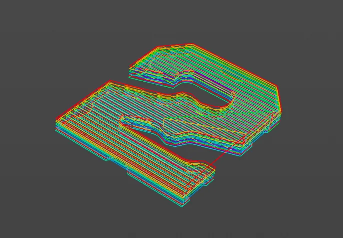
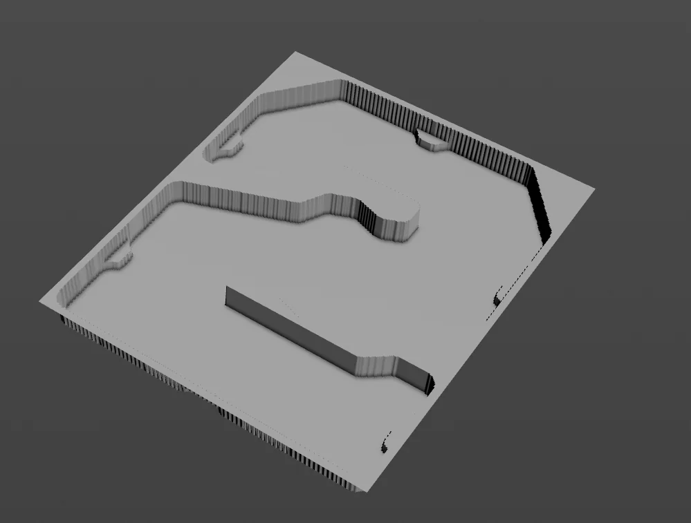
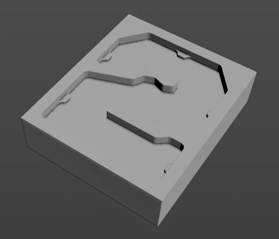
Overlaying the original geometry also lets you preview deviations that might result from mistakes or other parts of the process.
Analysis Stats
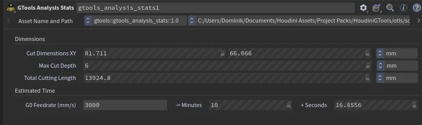
Allows you to get a rough estimate of how long the cut will likely take, along with the overall cut dimensions.
Check Z
Separates moves above and below the work surface, so you can easily distinguish travel moves from actual cutting moves.
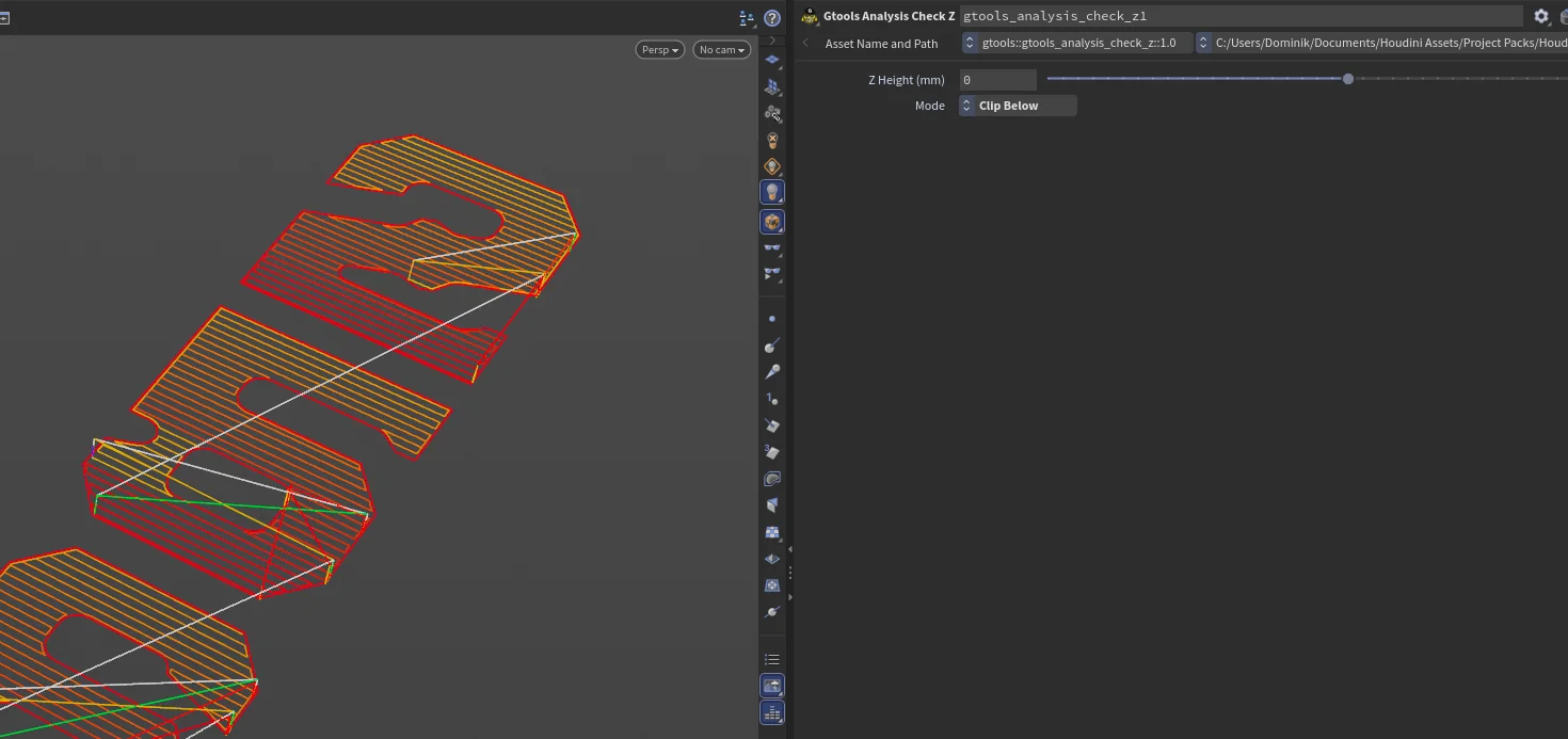
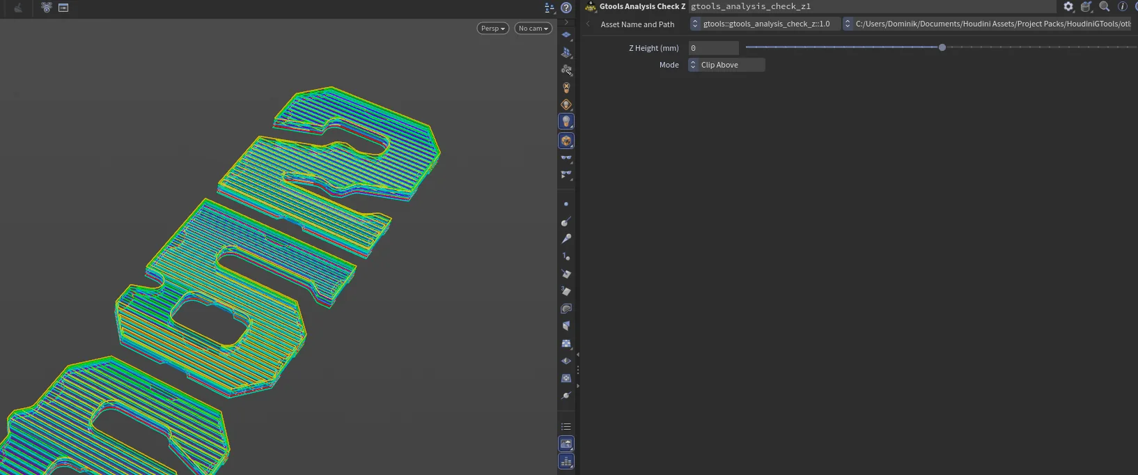
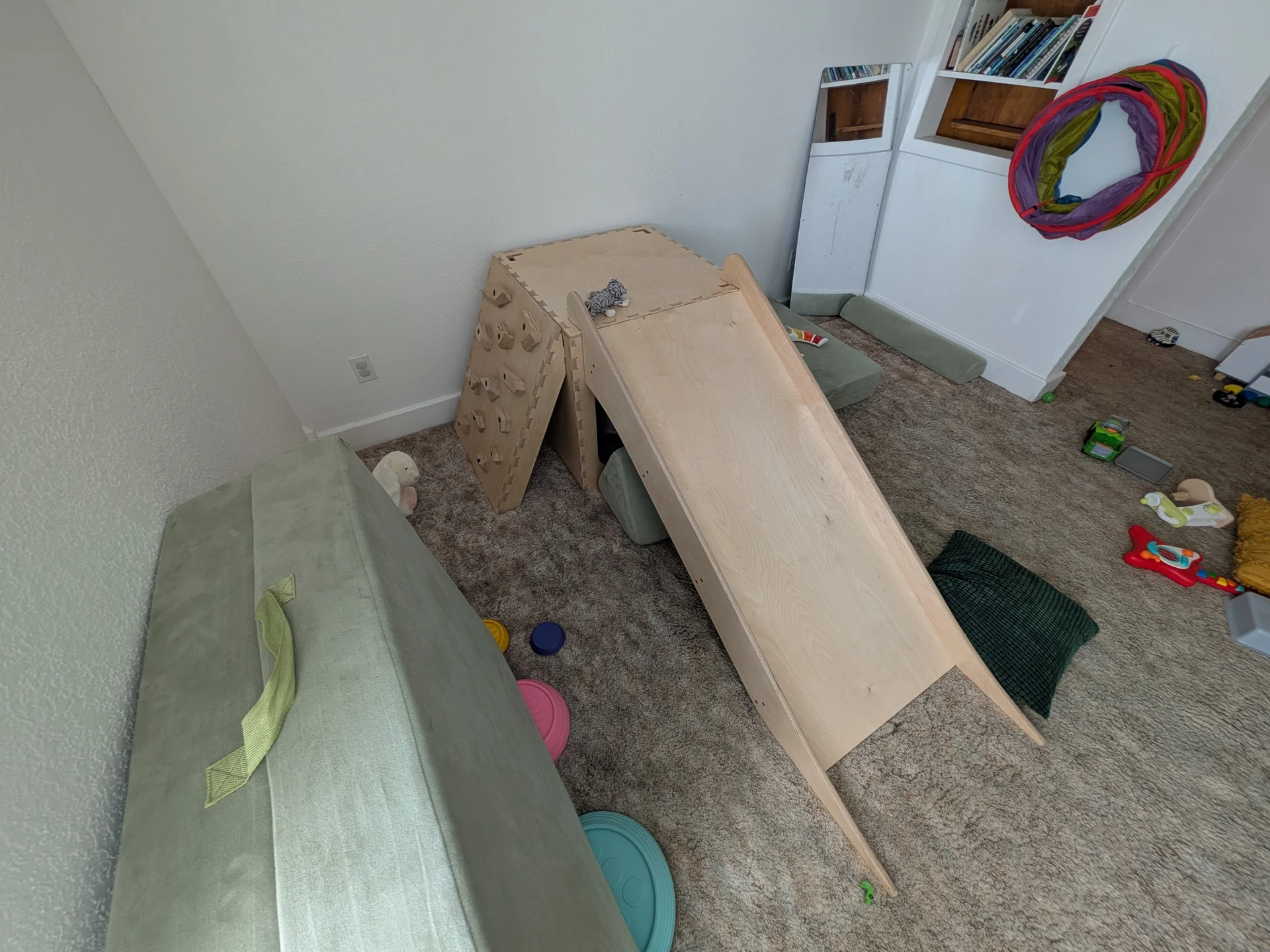
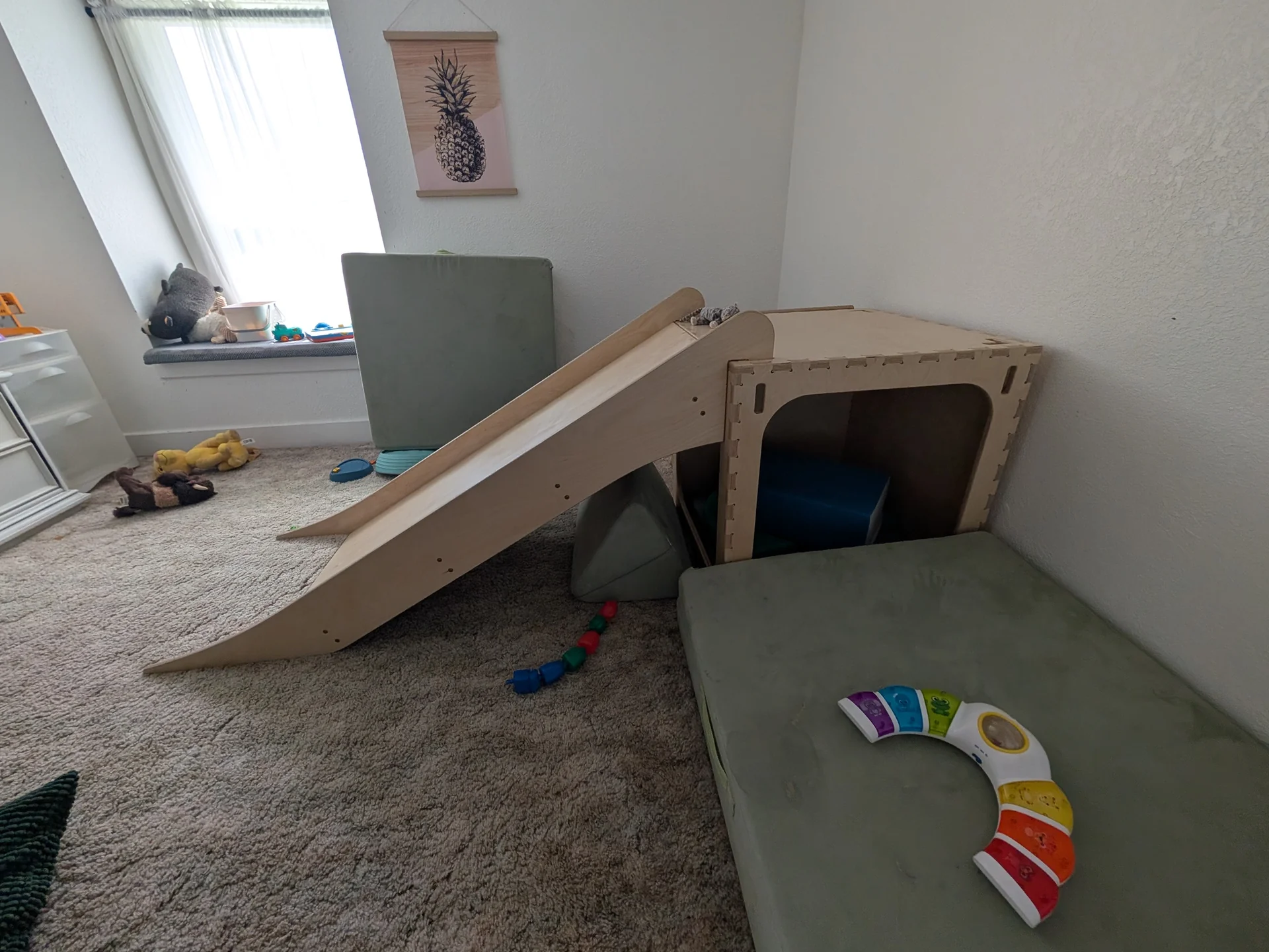
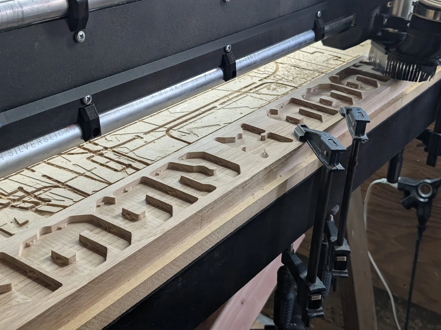
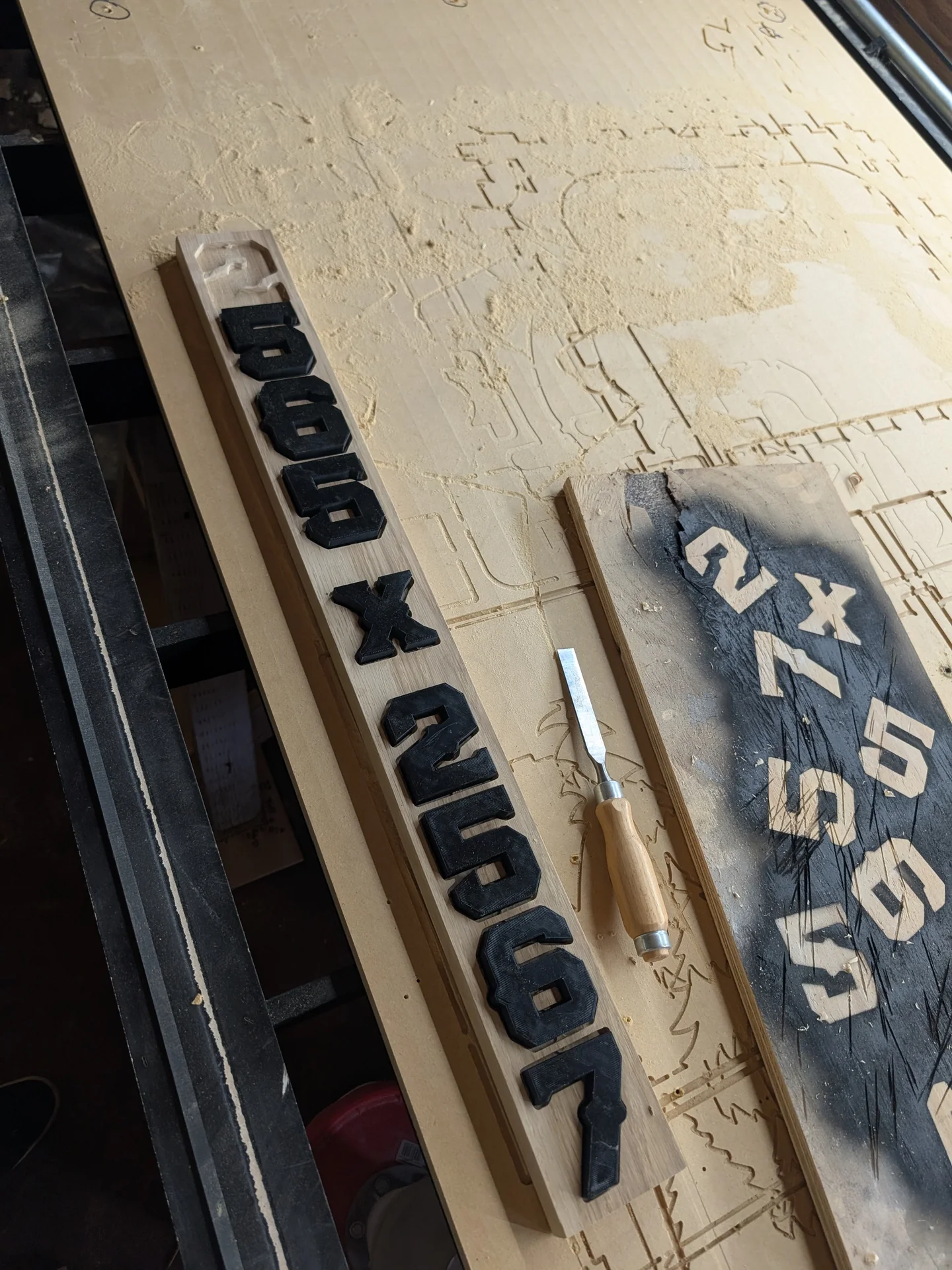
The toolset in action:
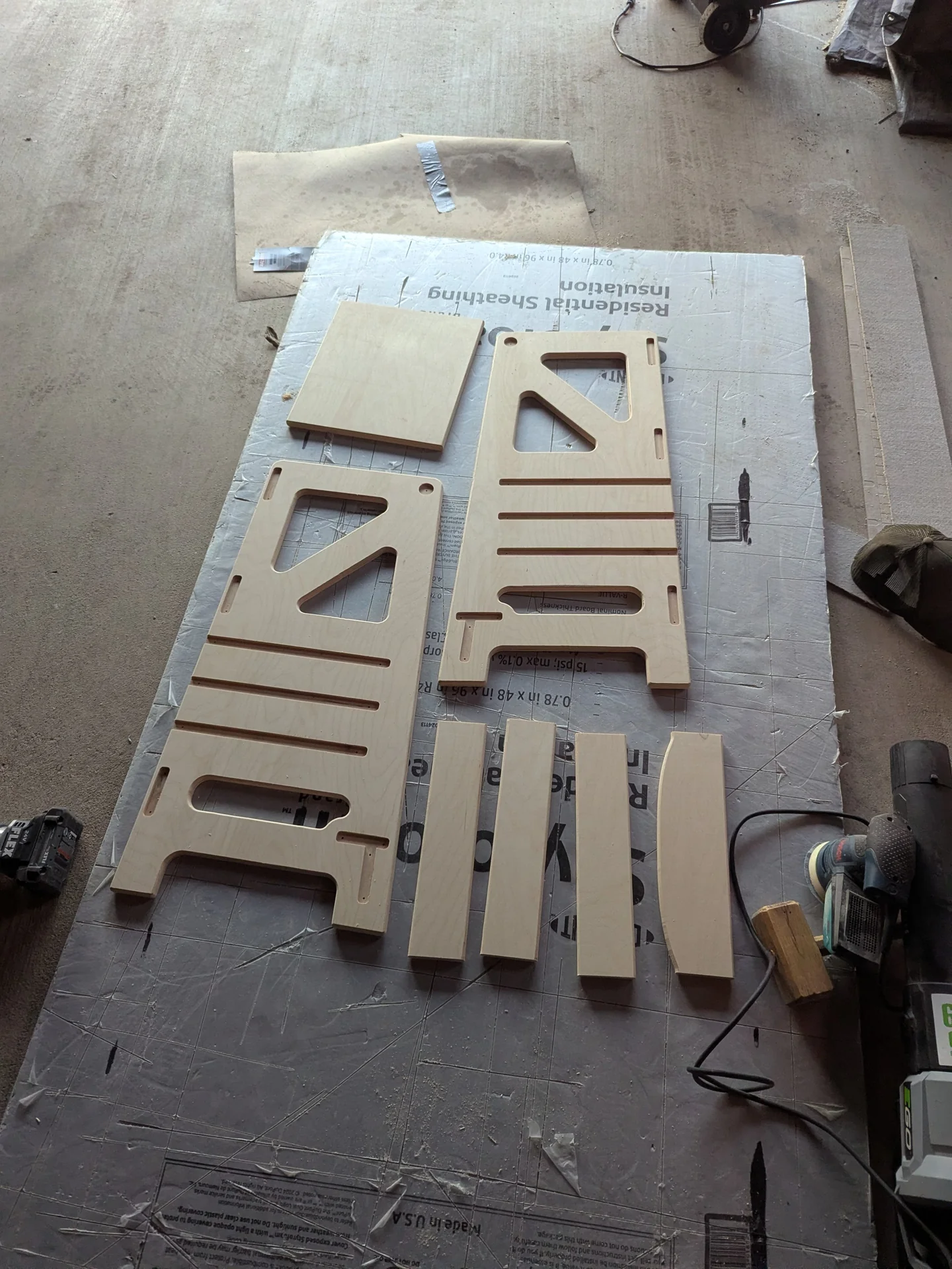
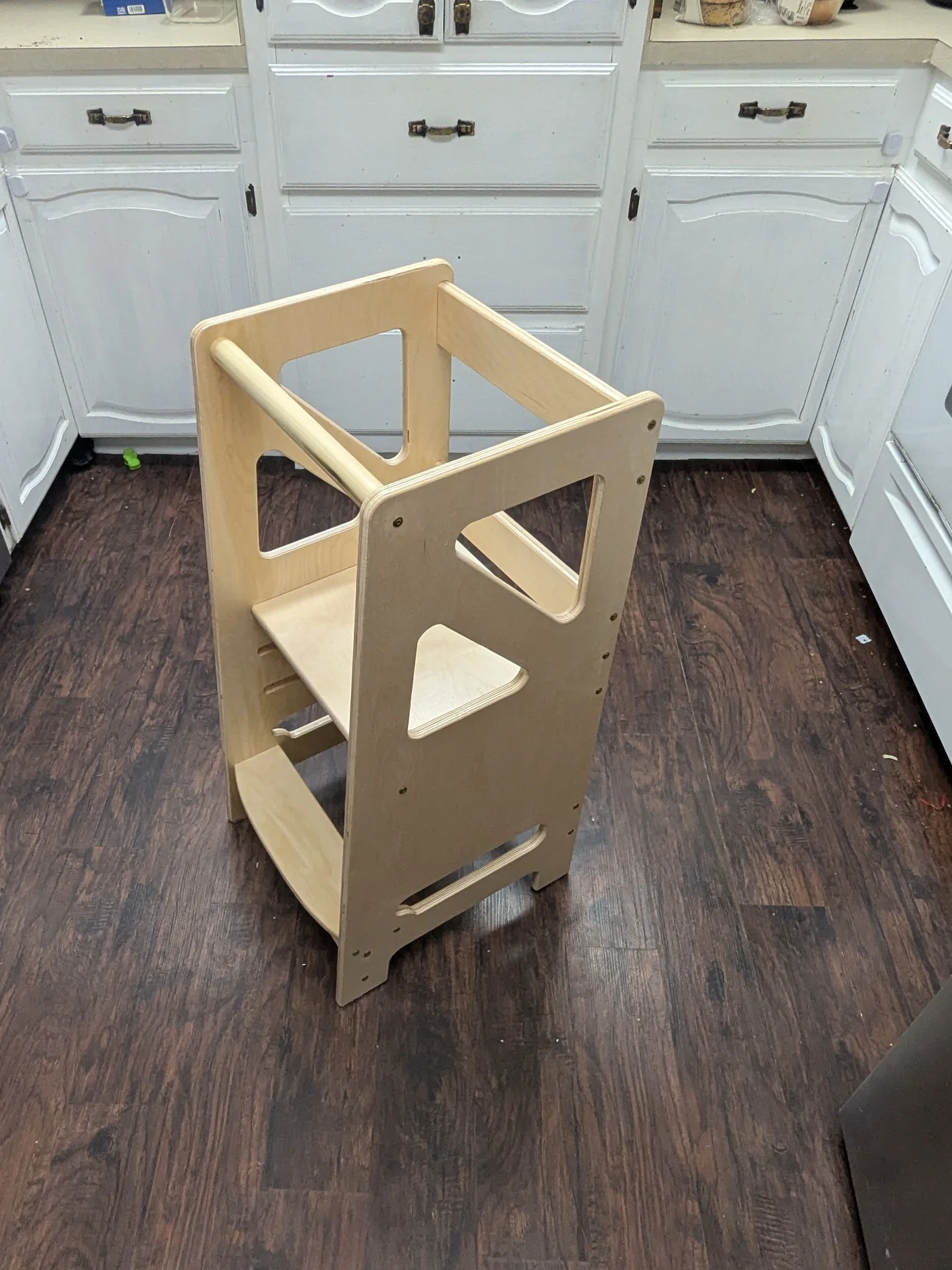

Final thoughts
This write-up is already lengthy, and there’s still a lot I didn’t cover. I worked on this project here and there over many months, making tweaks as I discovered things. I’d say it’s still far from perfect and could use some cleanup. But I was able to cut quite a few successful projects with this toolset, and it let me iterate and fine-tune my work in Houdini’s wonderful procedural environment.
I’d also love to add more features, like additional pocketing algorithms and 3D cuts (for non-planar surfaces or engraving, etc.). But who knows when or if I will get to that 😀
If you want to play with this toolset you are welcome to, but just be aware this should be considered experimental! Houdini G Tools